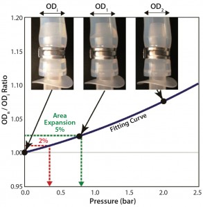
Figure 1: Swelling by internal pressure for tubing 2 (3/8-in. ID); calculation of swelling pressure from tube-swelling curve fitted by second-order polynomial fitting
Single-use systems (SUSs) are engineered process equipment solutions for pharmaceutical and biologics production. They offer several key advantages, such as lowering energy costs to reduce utility requirements, minimizing cleaning validation efforts, reducing water and chemical use, and enabling flexibility in manufacturing. Use of SUSs is increasingly popular in almost all fields of bioprocess applications (1, 2).
SUSs most commonly comprise components made of polymeric materials, which together create a system or unit operation designed for one-time or campaign use. Single-use assemblies are self-contained and preassembled plastic fluid paths, usually gamma irradiated for sterility and ready-to-use, built from a combination of standard components. Single-use assemblies can be customized to meet defined applications and unit operations. Components used for fluid management are individual parts designed to perform a particular function when assembled into the SUS (3).
One key difference between SUSs and traditional stainless steel piping systems is the pressure tolerance of the plastic components, which is generally lower than that of their stainless steel counterparts. Challenges of high-pressure operations with single-use assemblies have been reported in several applications: e.g., a sterile filtration integrity test (4), a final fill system (5), and a high-viscosity concentrated product flow stream (6). A system’s pressure rating is defined as its maximum allowable internal working pressure, whether for a vessel, tank, or piping used to hold or transport liquids or gases. It depends on the component’s materials of construction. Understanding pressure ratings for SUSs is critically important to ensuring their adequate operation in bioprocess applications.
One leak test currently used for disposable assemblies is based on a low-pressure hold (e.g., 0.025 bar) to detect leaks and defects to identify potential bag damage (7). A more sensitive test uses pressure <0.4 bar with small bags, detecting defects as small as 30 µm, with a restraining-plate design that supports flexible film containers (5, 8). Single-use bioprocess containers for large-scale applications have no similar high-sensitivity solution, but they have been tested using the low-pressure leak test in their point of use (9).
Pressures encountered by a single-use bioprocess system in use — e.g., hydrostatic pressure in large bioprocess containers, pump, or pressurized fluid transfers — may be
much higher than those of the above integrity tests. Single-use assembly designs and component materials must be specific to a given bioprocess application. Pharmaceutical-grade flexible tubing and connectors meet special process requirements for purity and consistency. But a number of issues and questions have been raised on the topic of pressure ratings for single-use assemblies.
The following reasons advocate for development of a single-use assembly pressure design guideline to accommodate bioprocessing conditions. First, tubing pressure performance data are reported only in terms of burst pressure (10). Second, expansion under pressure of tubing’s internal diameter (ID) has not been considered for adapter connections, although an increase in internal volume of tubing is not permitted in some applications. Third, although fasteners for connecting tubes and adapters/connectors are expected to maintain system integrity and prevent leaks (11, 12), no comprehensive pressure performance data for assemblies have yet been resolved. Finally, the risk of process failure by leakage or component damage is real because of the lower pressure resistance of polymer materials.
Here, we summarize the pressure rating of the key available components in single-use assemblies and compare them independently and when joined together. We tested several pharmaceutical-grade tubing types and evaluated them for appropriate operation pressure with fastener integrity during the lifetime of each gamma-irradiated assembly. Our case study demonstrates pressure ratings for single-use filtration systems. And we propose a pressure-specification guidance to align the SUS design pressures with required bioprocess operation pressures.
Performance Testing
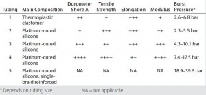
Single-Use Tubing: Table 1 lists our tubing specifications for five types of pharmaceutical-grade material with ID dimensions from 1/8 inch to 3/4 inch and various wall thicknesses. Physical properties are compared for elastomer and extruded tubing. Sample hardness (durometer) varies: tubings 1 and 2 are relatively soft, whereas tubings 4 and 5 are quite hard. Smaller-diameter tubing is able to withstand higher pressures across all types than wider tubing can. But burst pressure does not correlate directly to a pressure-rating recommendation when the tubing is used for a bioprocess application. Furthermore, pressurization expands tubes and will affect their engagement with fittings. No clear empirical evidence supports pressure rating recommendations for bioprocess operations; however, tubing manufacturers recommend a maximum operation pressure at 20–30% of the burst pressure.
To measure tube swelling at high internal pressures, we implemented an air-pressure hold test. This required connecting a Triclamp (TC) adapter and a plug end adapter to opposite ends of each 15-cm length of gamma-irradiated tubing with stainless steel single-ear (SSSE) clamps for both hose-barbs. An AMETEK Model T-975 hand pump connected to the TC adapter supplied compressed air. An AMETEK Jofra IPI300C-B sensor detected pressure inside the tubing, and we used Mitutoyo CD-30C Vernier calipers to measure tubing size. Because tubing profiles are not always uniform, we measured the tubing diameters from three or four directions and applied an average number to calculate the swelling ratios, with a five-minute hold time before each measurement when pressurizing the tubing.
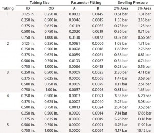
Tubing diameters increased with added pressure, as Figure 1 shows, based on an outer diameter (OD) ratio defined as ODpressurized/ODatmospheric. When a tube’s diameter increases with pressurization, its contact area with the barb adapter decreases, increasing the risk of connection failure. We assessed the change in size of each tube’s cross-sectional area (calculated from outer diameter) as a function of pressure and compared it with the tubing’s maximum working pressure. To predict the tube diameter from operating pressure, we fitted our results by a second-order polynomial curve (Figure 1). OD ratios of 1.01 and 1.025 are comparable to cross-sectional area increases of 2% and 5%, respectively.
Table 2 summarizes calculated pressures for 2% and 5% expansion in each tubing type and size. The degree of swelling with pressure depends on tubing type. Tubing 2 measurements were very close to those of tubing 1 at all sizes. Tubing 4 showed a smaller expansion than tubing 3, and both were considerably lower than tubings 1 and 2. Braided silicon tubing (tubing 5) showed the best performance (the smallest ID change with pressure). Its pressure from 5% swelling is comparable to roughly 20–50% of tubing burst pressures (Table 1). That exceeds the maximum recommended pressure of some of the other tubing tested.
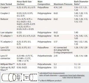
Hose-Barb Connections: Single-use assemblies commonly use plastic components to connect desired tubing. Table 3 lists single-use components we tested. Each item’s pressure specification should ideally satisfy the maximum operation pressure of a given bioprocess application.
Disposable capsule filters often are assembled in SUSs for bioprocess use. Uniquely, sterilizing-grade capsule filters can be coupled with gamma-irradiated disposable containers into process assemblies, an advantage for assuring sterility. Capsule filters come in a broad range of filter media and surface areas. For assembling SUSs, however, inlet and outlet hose-barb configurations for capsule filters are limited. To minimize leak risk, a larger hose barb (9/16 inch) can connect 1/2-inch tubing. A secure and reliable connection depends on how well the fitting and tubing work together. All listed items in Table 3 have a hose barb for securing tubing, which improves both seal and grip for different grades of tubing available.
We express the hose-barb height of each component as a ratio between the outer diameter of its maximum barb arc and the tube’s internal diameter. If the ID of pressurized tubing exceeds the maximum diameter of the hose barb, then that tubing will loosen and could leak. Finding the proper tubing connection with an appropriate pressure target is essential for a safe and secure SUSs.
The OD ratio must be controlled during tube swelling so that it does not exceed the ratio of barb diameters (Table 3) for any component. OD ratios of 1.01 and 1.025 are smaller than all connector barb-diameter ratios. The pressure for 2% swelling is more in line with manufacturer recommendation to maintain working pressure <30% of burst pressure. The 2% swelling pressure in Table 2 therefore can be used as a guideline for each tubing type and size. Tubings 4 and 5 show the least expansion with pressure, making them the best choices for high-pressure bioprocess applications.
Fastener Integrity: SSSE clamps provide a means for securing tubing to hose-barb connectors. Clamps come in a range of sizes and provide 360° compression of tubing around the hose barb to minimize the leak potential of a single-use assembly. Based on tubing maximum and component working pressures, we systematically evaluated the probability of failure at a connection caused by elevated internal pressure. With SSSE clamps in use, the typical burst points of single-use assemblies are not at the hose-barb clamp connection, but rather in the tubing or other components. However, one root cause of leakage problems in bioprocess applications is often the tubing–connector junction (13).
We tested different combinations of tubing and corresponding hose-barb connectors with SSSE fasteners (Table 1, Table 3) using pressure hold for a bubble-emission test. Each air-pressurized assembly was submerged for five minutes in water and observed to detect bubble leaks. To support shelf-life claims, we used real-time assembly aging for two years of storage after gamma irradiation (>45 kGy). Pressurization came from the same equipment as in the tube-swelling test, above. We chose a test pressure based on the lower of either the tubing maximum operation pressure or component maximum pressure, then selected four operating pressures: 100%, 80%, 70%, and 50% of that lower maximum pressure.
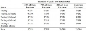
Table 4 shows the results of our comprehensive pressurization study joining each tubing and connecter with an SSSE fastener. We tested each assembly after gamma irradiation two or three times during its two-year shelf life. Most SSSE clamp connections worked well with all tubing and barb combinations up to the maximum pressure tested. Thus, the burst pressure of an assembly using SSSE clamps can be dictated more by the maximum pressure of the tubing or the connector than the SSSE connection.
At the maximum pressure, we could detect leakage in only 1.2% of assemblies. At half the maximum pressure, the probability of leakage drops to 0.011%. High-pressure tubings 4 and 5 had slightly higher leakage rates than the softer tubings, but the half pressure of the former exceeds the maximum pressure range of tubings 1 and 2. Therefore, the pressure range of tubing and components is likely to be a better determinant of leakage probability than their materials of construction and components. Our results further suggest that higher-pressure operations with single-use assemblies are more likely to leak; to minimize leaks, lower-pressure operations are favored. If high pressure is required for a given application, then selecting the high-pressure components and tubing and adopting a relatively lower range for operation should reduce leak risk. We also recommend an additional preuse leak test for tubing assemblies at process pressure during design qualification (13).
We also evaluated the results in Table 4 based on the assembly shelf life (data not shown). Although plastic components and tubing are assumed to weaken after gamma irradiation, we found no obvious difference in leakage probability after such treatment. It is generally accepted that within two years of shelf life, the pressure performance of gamma-irradiated assemblies is maintained.
We also evaluated filter connections with all types of tubing in nonirradiated assemblies and found no leakage in 13 tests at <2 bar. However, two of five tests failed with a Millipak filter assembly at >3 bar pressure, both from tubing 5 — one with a 1/4-inch hose barb and one with 9/16-inch. When results are summarized by test pressure, our conclusion here is similar to that from Table 4: Leakage probability increases at high pressure. Based on our limited data set — and in conjunction with the more favorable connection results in Table 4 — we suggest using TC connections rather than hose barbs for filter assemblies that may see high-pressure applications >3 bar.
Containers and Bags: We evaluated bioprocess containers made of PureFlex film from EMD Millipore with a burst test (“Specifications’ box”). It is a high-purity, medical grade, coextruded film designed to provide strength, flexibility (with maximum resistance to flex-crack), an excellent gas barrier, and inert product contact. Large-volume containers are used with drums or bins to support the weight of process liquids in them. Suppliers use a low-pressure leak test to detect defects in qualifying bioprocess containers. Indeed, thin-film containers are restricted to a low-pressure test. A gap remains in which such test pressure will not satisfy that of process operations, especially for applications such as pressurized fluid transfer and filtration. Understanding the pressure limits of bioprocess containers also is important for processes involving cytotoxic or otherwise dangerous substances.
| PureFlex Single-Use Container Specifications |
| Main Composition: Low-density polyethylene, polyethylene vinyl alcohol copolymer, ethylene vinyl acetate
Film Thickness: 0.0105 inch Tensile Strength (ASTM D882): 186 bar (2,700 psi) Elongation (ASTM D882): 570% Yield Strength (ASTM D882): 94 bar (1,360 psi) Modulus (ASTM D882): 2,550 bar (37,000 psi) Seam Strength (ASTM D882): 32 N/cm |
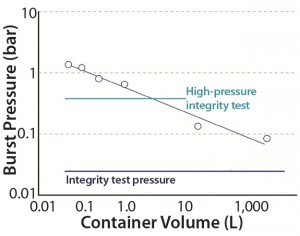
We conducted an overpressure study for single-use containers by introducing compressed air at 0.05–0.2 bar pressure. An OKANO POP-202 digital manometer measured pressure change inside each container. We tested two-dimensional (2D) containers on a table and three-dimensional (3D) containers installed inside a bin. Figure 2 lists results of this overpressure study for bags of increasing volume (n = 1 for each size).
Burst pressure was higher for smaller bags and decreased with increasing container size. Larger-volume bags have greater surface area on each side. The data points are approximately linear on a double-logarithmic graph, so we surmise that burst pressure can be reasonably estimated from container size.
Burst pressure of containers up to 1Â L is higher than the test pressure used in a high-pressure integrity test (HPIT); however the bags are supported structurally with restraining plates during the test. The burst pressures of 0.15 and 0.08 bar for 20-L and 2,000-L bags, respectively, were significantly below the HPIT pressure but higher than the low-pressure leak test measurement. Large 3D bags thus are suitable only for the low-pressure leak test. Also, the 3D containers rely on bins for structural support, so they should be used only at atmospheric pressure. Such containers should not be filled above their design volume, but if users must do so, then vent filters or liquid sensors would be essential for safe and rupture-free operations.
Case Study of a Single-Use Assembly
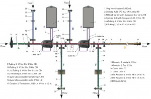
We evaluated the design of a single-use redundant filter (SURF) assembly for bulk drug-substance or final drug-product sterile filtration, comparing the operation pressure of each flow path against the pressure rating for each component. SURF operations include multiple steps at different operating pressures: venting, wetting, draining, pre- and postuse filter integrity testing, air drying, and product filtration. The SURF design in Figure 3 comes from a previous case study (14, 15). Operating pressures follow the optimized sequence from a reference document (16), and the pressure rating of the SUS is the lowest of its components’ pressure ratings. That is a design consideration using a risk-based approach for assessment of process compatibility (13).

Table 5a: Filter-operation pressure and pressure rating of flow path A; safety factor = pressure rating Ă· operation pressure

Table 5b: Filter-operation pressure and pressure rating of flow path B; safety factor = pressure rating Ă· operation pressure
Table 5 compares filter-operation pressures and flow-path pressure ratings. Tubing dictates the pressure rating for all flow paths except the bag assemblies. In each case, the pressure rating satisfies the operation pressure for each flow path, including some safety factor. The lowest flow-path pressure rating is for the vent-bag parts of flow path E (Table 5e).
The safety factor for filter-inlet flow paths A and B are a bit lower than that of the others. Flow-path B is exposed to high air pressure during the filter integrity test.

Table 5c: Filter-operation pressure and pressure rating of flow path C; safety factor = pressure rating Ă· operation pressure
A preuse tubing leak test would verify the integrity of such a flow path. The pressure tolerance of flow-path A is limited by tubing 3, for which the pressure identified with a 2% cross-sectional area swelling (Table 2) was 1.1 bar. That mostly satisfies the operation pressure, but it is well below the system’s maximum operation pressure of 3.45 bar.
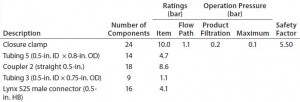
Table 5d: Filter-operation pressure and pressure rating of flow path D; safety factor = pressure rating Ă· operation pressure
If >2% swelling is acceptable on design qualification, then the flow-path A assembly could fully satisfy the application’s requirements. If not, then users should consider changing the tubing used to a Braded silicon or adding a preuse tubing leak test.

Table 5e: Filter-operation pressure and pressure rating of flow path E; safety factor = pressure rating Ă· operation pressure
For a complete filter blow-down, we recommend air drying with 4-bar compressed air to exceed the bubble-point pressure of the filter. This requires a higher pressure rating for flow-path F in particular, in which the filter connection and tubing types must be changed to satisfy the high pressure requirement. Filter blow-down pressure also reduces the safety factors for flow-paths B and C.

Table 5f: Filter-operation pressure and pressure rating of flow path F; safety factor = pressure rating Ă· operation pressure; TC connection is used for both Millipak barrier filter inlet and outlet (not described in Figure 3).
Consider vent bags to be the weakest component of these assembly designs. Choose an appropriate size to receive the vented air and wetting fluid without maximum expansion. If your required volumes or operation procedures create a risk of bag rupture, you can examine several options for solving the problem: e.g., changing the size of the vent bag, using a hard plastic bottle, or adding a vent filter to the bag outlet.
Recommended Testing
Our study focused on the pressure ratings of SUSs and their components. We identified some design guidance to help users attain suitable pressure tolerance in bioprocess applications. Pressure ratings described for the tested single-use components and assemblies reveal the sensitivity of SUSs to process pressure compared with traditional stainless steel systems with their much higher pressure tolerances. During the design qualification stage of a bioprocess application, users should consider tube swelling at high pressures, the probability of leakage from tubing fasteners, and the need for an available low-pressure leak test for single-use assemblies. Those steps are crucial to minimizing the risk of process failure due to a leaking assembly. We found a SURF case study to be helpful in understanding the pressure challenge and how to
implement risk mitigation during design review. Such reviews of assembly design are essential to adapting bioprocess applications and process requirements for efficient, low-risk single-use solutions.
Acknowledgments We thank Kuniyo Ono and Taichi Hanada for assistance with the pressure test, Mika Araki and Nessima Bardak for component preparation, John Gugliotti for the test-matrix idea, and John Saragosa, for discussions.
References
1 McLeod LD. The Road to a Fully Disposable Protein Purification Process. BioProcess Int. 7(4) 2009: S4–S8.
2 Sinclair A, et al. The Environmental Impact of Disposable Technologies. BioPharm Int. 21(11) 2008: S4–S15.
3 Lopes AG. Single-Use in the Biopharmaceutical Industry: A Review of Current Technology Impact, Challenges and Limitations. Food Bioproducts Proc. 93(1) 2015: 98–114; doi:10.1016/j.fbp.2013.12.002.
4 Lentine KR, et al. Preparation of Redundant, Disposable Filtration Systems. BioProcess Int. 4(6) 2006: S44–S47.
5 Application Note TB1052EN00, Rev. A: High Sensitivity Integrity Test for Manufacturing Release of Mobius Single-Use Fill Finish Assemblies. EMD Millipore: Billerica, MA, June 2012.
6 Hutchinson R, Matthews T, Sugahara J. Fully Automated Single-Use Tangential Flow Filtration for the Formulation of Biologics. Am. Pharma. Rev. 13(7) 2010.
7 Stering M, et al. Point-of-Use Disposable Bag Testing. Gen. Eng. Biotechnol. News 33(11) 2013.
8 Detroy A, et al. Single-Use Technology for Syringe Filling. BioPharm Int. eBook, March 2014: S24–S30.
9 Sokolnicki A. A Method for PreUse Integrity Assurance for Single-Use Process Containers. IBC Biopharmaceutical Development and Production Conference: Huntington Beach, CA, March 2015.
10 Malczewski RM, Inman WD Jr., Cadieux BL. Burst Strength Testing of DOW CORNING® Brand Pharma Tubings. Dow Corning Healthcare: Hemlock, MI, 2003.
11 Get a Grip! An Introduction to Hose Barbs. Colder Products Company: St. Paul, MI, 2007.
12 Single-Use Connections Guide. Integra Companies Inc.: Devens, MA, 2010.
13 Repetto R, et al. PDA Technical Report No. 66: Application of Single-Use Systems in Pharmaceutical Manufacturing. Parenteral Drug Association, Inc.: Bethesda, MD, 2014.
14 Rolfe S, Love T, Walker S. Implication to Consider with the Adoption of Single Use in Final Fill (poster). 247th ACS National Meeting: Dallas, TX, March 2014.
15 Love T. Adoption of Single-Use Final Filtration Assembly, Points to Consider. AIChE Annual Meeting: Atlanta, GA, November 2014.
16 Patil R, Felo M, Oulundsen G. Single-Use Redundant Filtration. Pharm. Technol. Eur. 24(3) 2012.
Corresponding author Takao Ito is associate director of the biomanufacturing sciences network for Korea and Japan at Merck Ltd. Japan, DiverCity Tokyo Office, Tower 15F, 1-1-20 Aomi, Koto-ku, Tokyo 135-0064 Japan; 81-120-013-690, fax 81-3-5434-4827; takao.ito@merckgroup.com. Adam Sokolnicki is a biomanufacturing engineer at EMD Millipore, 290 Concord Road, Billerica MA 01821; 1-781-533-6000. Terri Love is a biomanufacturing engineer at Merck Millipore Ltd., Tullagreen, Carrigtwohill, County Cork, Ireland; 353-1890-924-645, fax 353-1890-924-884.

