Ultrafiltration (UF) is a membrane-based separation technology commonly used in the biopharmaceutical industry for concentration or diafiltration of protein solutions to remove low–molecular-weight (LMW) impurities or exchange buffers. The nominal MW limit of UF membranes ranges from 1,000 Da (1 kDa) to 1,000,000 Da (1,000 kDa). A target product is retained by the membrane while lower-MW solutes or impurities pass through (1). For a target product with a smaller MW than the impurities, separation is accomplished by allowing the product to pass through the membrane into the permeate side instead.
One key factor that influences robust and successful operation of an ultrafiltration process is integrity of the membrane assembly. An integral membrane system is required not only for achieving desired product yield and purification during process operation, but also for ensuring process consistency and adherence to good manufacturing practice (GMP) guidelines across multiple batches during a production campaign. An integral UF membrane system may be defined as one that retains a target product (or impurity) to a very high degree with minimal effect on process yield and recovery. Broadly speaking, a nonintegral membrane system can result from a damaged membrane or module, incomplete sealing of the membrane in its holder or assembly, and/or incorrect installation of the membrane module in that holder. Flat-plate, spiral-wound, and hollow-fiber UF membranes can be incorporated into modular formats as well.
PRODUCT FOCUS: BIOPHARMACEUTICALS
PROCESS FOCUS: DOWNSTREAM PROCESSING
WHO SHOULD READ: ANALYTICAL AND DOWNSTREAM PROCESS DEVELOPMENT
KEYWORDS: DIFFUSION TEST, MEMBRANE FILTRATION, CASSETTES, AUTOMATION, PRESSURE
LEVEL: INTERMEDIATE
Membrane manufacturers often use a number of tests to ensure membrane and module integrity during their manufacturing process. Prominent among such tests are those measuring membrane-retention profiles and modular integrity. Membrane retention is tested using a protein solution or a solution of markers with known MWs. Mixed dextran solution is a common marker used for UF membranes and modules (2). Membrane-retention tests confirm that manufactured membranes fall within their correct cut-off specifications before product release. End users (manufacturers of drugs and vaccines) integrity test UF modules in a system to ensure proper installation and integrity of both membrane and module before committing expensive product streams to the system for processing. That is not only prudent from an economic perspective, but it also serves to conform with current good manufacturing practice (CGMP) guidelines.
Here we focus on describing best practices in end-user integrity testing (below, simply referred to as integrity testing) of UF systems and assemblies (membrane, module, and related piping) used in biopharmaceutical manufacturing.
Equation 1:
Ficks’ law of diffusion, in which K = solubility/diffusivity coefficient, P1 and P2 = pressure difference across the system, r = membrane porosity, L = effective path length, and A = membrane area

Integrity Test
Integrity testing is critical to ensuring a robust and reliable UF process operation. An integrity test is designed to confirm that
- there are no major defects in membrane or module
- modules are installed properly in the system
- all gaskets are sealed properly
- the feed/retentate side of the process is isolated from the filtrate side (3).
Preuse integrity testing helps mitigate the business risk of potential batch loss if filter performance is compromised by filter damage during shipping, storage, or installation (4). For UF systems that will be reused many times, filter assemblies are often tested after processing, usually after cleaning but before storage, to check for process- or cleaning-induced failures. Relatively convenient testing at that point can save time in testing before the next run. If a UF system is brought out of storage after a period of disuse, it would be prudent to verify the integrity of that system before using it.
For sterilizing-grade filters, a correlation can be drawn between bacterial retention and integrity test results (using bubble-point or diffusion testing). But UF membrane integrity testing is not designed to strictly correlate with the retention or passage profile of any target marker or product. Instead, such tests relate more to membrane sealing in their modules and detecting gross defects or leaks in a system after installation.
Common methods used traditionally for membrane systems and assemblies are bubble-point, diffusion, and pressure-hold tests. Applying a bubble-point test to UF membranes is problematic, however. Bubble points (air–water) for UF membranes are typically very high (>200 –500 psi) because of the small pore size (
The pressure-hold test measures air-pressure loss across a wetted membrane over a given time. Some users prefer this method because it requires no measurement of air flow by a mass flow meter. The important consideration here is the pressure venting at the end of the test. With the outlet valve closed, an entire system is brought to the test pressure (typically 10–30 psig). If the pressure is relieved upstream, then the downstream pressure will create back-pressure across the membrane and thus irreversibly damage it.
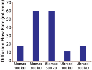
The most common integrity test for UF membrane assemblies is the air–water diffusion test. A lthough its results do not correlate directly with protein retention, they still usefully indicate the absence of gross leaks in a system. But it does not indicate membrane pore size or molecular-weight cut-off (MWCO) (Figure 1).
Diffusion Test Method
During diffusion testing, a UF membrane is wetted and pressurized with air to a predetermined test pressure. The air dissolves and diffuses through the wetted membrane due to differential pressure across it.
Air flow is measured directly on the downstream side or on the upstream side after equilibration. The amount of air flow is proportional to the differential pressure, membrane porosity, and membrane area — and inversely proportional to water-layer thickness (
Equation 1).
For an integral membrane, the downstream air-flow rate (during an air–water diffusion test) primarily comes from diffusion of air through wetted pores. The downstream air-flow rate in a nonintegral membrane is mostly attributable to defects that are much larger in size than the membrane pores. Defects in a nonintegral membrane generate convective air flows that are significantly higher than the background diffusive flow and may exceed the diffusion test specification beyond a certain threshold defect size (5). For example, if a membrane had a defect of 5 µm, the bubble point required to maintain water in its pores would be
For a small-scale system, it is often convenient and practical to manually measure downstream diffusion flow by capturing the air flow in a submerged, inverted, volumetric cylinder during a specified time. For large UF systems with >10 m2 installed membrane area, a mass flowmeter (upstream or downstream) is commonly used to measure diffusive air flow directly through the membrane.
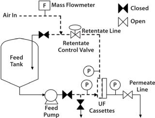
Diffusion results tend to be comparable regardless of the placement of the air flowmeter, whether upstream (feed/retentate side) or downstream (permeate side) of a UF skid. However, it is more convenient to place the mass flowmeter on the upstream line (Figure 2) to prevent liquid ingression into the permeate lines, which can damage the instrument. Many air-mass flowmeters are sensitive to moisture. If one needs to be placed in the downstream or permeate side of the skid, associated piping may need to be designed with special precautions that prevent moisture ingress. For example, a vessel or a trap for moisture could be placed before the air-mass flowmeter.
Significance of Diffusion Test: The air–water diffusion test is designed to detect gross defects in a filtration system. However, to detect membrane defects, the viscous flow value on top of background diffusion flow must be determined. (A defect hole is significantly larger than a pore and can represent either gross damage that allows substantially detectable flow or marginal damage that is detectable only by the most sensitive methods.)
For example, the 10-kD Pellicon 2 regenerated cellulose cassette with C-screen has a diffusion specification of 70 mL/min/m2 when tested at 30 psig (6).
Considering a worst-case situation in which all of that flow rate is contributed by convective gas flow through a single hole in the membrane (not including the integral membrane diffusional gas flow), the defect diameter (smallest detectable hole) can be calculated as a 54-µm cylindrical flaw using the model of isentropic, compressible choked flow through an orifice (7). The liquid flow through the same cylindrical channel is estimated as 6.5 mL/min (according to the Hagen–Poiseuille Law).
For a 1-m2 membrane system operating at 60 LMH with 15-psig transmembrane pressure, the defect flow would represent ∼0.6% of the total process flux. Hence, liquid flow through the defect would be impossible to detect. Assuming that the integral surface area is completely retentive, for a five-diavolume process, such a defect would compromise retention to 99.4%, giving ∼3% yield loss. For a larger membrane area with the same defect size, the loss would be significantly smaller because the liquid flow is balanced by the increasing amount of integral surface area (4).
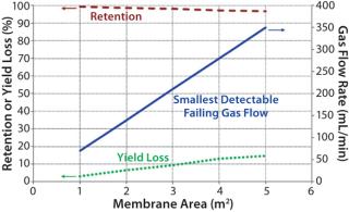
The smallest detectable defect increases with a larger membrane area. Figure 3 shows that the possibility of detecting a certain defect size (as indicated by the corresponding smallest detectable failing flow) drops as the membrane area increases. Although the decrease in retention may appear to be small (<5%), its effect on yield loss could be significant based on the extent of processing (e.g., concentration factor and diafiltration volumes). As such, integrity testing large UF systems is important to minimize losses in process yield.
Process Conditions, Critical Factors, and Best Practices
Several factors affect diffusion flow results obtained during integrity testing. Some of the critical factors are discussed below.
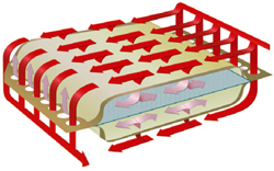
Sealing: Cassettes have more or less become the default membrane module format for UF applications in the biopharmaceutical industry (Figure 4). UF cassettes are made of individual packets of feed screens/spacers, membrane, and permeate-screens/spacers. When cassettes are installed into a holder, a proper seal must be maintained between packets to prevent internal (feed to permeate) and external (leaking) fluid bypass. Cassette installation requires intercassette silicone gaskets between each module and the holder end-plate to form a correct seal. Some modules — e.g., Merck Millipore Pellicon 3 cassettes — are manufactured with integrated thermoplastic elastomers that eliminate the need for external gaskets (8).
For holders that have (center block) manifolds with filtrate grooves, a stainless steel support plate is required to provide additional support for proper module sealing (Figure 5). Incorrect combination of plate, gaskets, and torque (or compression) can lead to improper sealing of the cassettes. Sealing problems can be detected easily with a postinstallation air-diffusion test. When installing a UF module with a stainless steel plate, the best practice is to use a sufficiently thick (0.088 in.) gasket adjacent to the manifold and plate to ensure proper sealing.
#f7f7f7;color:#000000;” >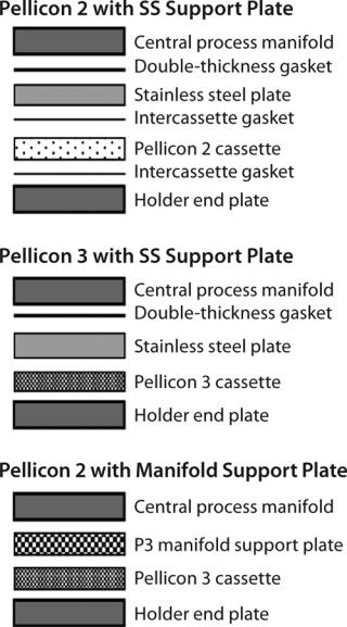
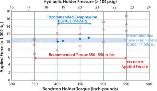
Typically, a compression of 10,000–11,000 pound-force (lbf) is recommended to ensure that UF modules are sealed properly. For a Merck Millipore process-scale holder with a hydraulic closure (FCUF-2281 or FCUF2271), that translates to a hydraulic pressure of 1,870–2,050 psig. That pressure is converted to compressive force by hydraulic cylinders. For a bench-top holder, the recommended torque of 350–550 in-lb is transmitted into compressive force by tie rods and nuts.
Equation 2:
Where N = diffusion flow rate (mL/min), ttest = test time (min), Patm = atmospheric pressure (14.7 psi), Vu = upstream volume (mL), and ΔP = pressure change (psi)

Figure 6 compares total forces applied on UF modules at recommended hydraulic pressure and manual torque. The recommended manual-torque range gives higher compressive force to account for loss due to the increased friction of used holder nuts. The figure graphs the decrease of applied force with an increase of friction factor. The friction factor of new, dry bronze nuts is ∼0.23, which increases to ∼0.26 for used bronze nuts and ∼0.35 for an unmaintained holder. If a holder is not adequately torqued, there will be a direct air passage from retentate to permeate, and the resulting sealing issue can cause test failure.
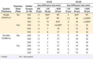
Gasket Thickness:A study was performed on bench-scale holder using a single Merck Millipore Pellicon 2 unit, with 10-kD and 30-kD Ultracel regenerated cellulose membrane to test different gasket and stainless steel support plate combinations under three different torques (350, 450, and 550 in-Ib) to determine the impact of gasket and cassette compression on diffusion value (9). Installation with single thick (0.044 in) gaskets but no stainless steel plate failed at least one diffusion test pressure at all torque settings. The diffusion value decreased with increasing torque, so the seal between cassette ports and the gaskets/holder can be further compressed. Adding a stainless steel plate between the plate and gasket clearly improved sealing, passing the diffusion test at a torque of 450–550 in-lb. The results (Table 1) also indicate that combining a sufficiently thick (0.088 in) gasket with or without a support plate gives robust sealing and consistently passes diffusion tests.
Table 1: Diffusion and retention test results for different gasket and torque combinations
Compression and Test Pressure: Sensitivity of a diffusion test at different pressures has a relationship with the minimum required compression force for process-scale holders. When a UF system is integrity tested at 10 psig, the diffusion test can detect gross defects with bubble points lower than the test pressure or defects that open at that pressure. However, the test cannot detect defects that open up at higher operating pressures (e.g., 50 psig), unless the diffusion test is performed at such a pressure. The diffusion test sensitivity increases nonlinearly with higher test pressure as viscous flow through defects contributes more to the total measurable flow.
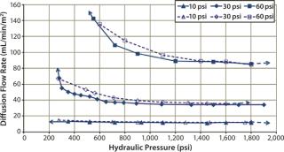
Another study investigated sensitivity of the diffusion test to detect sealing defects from insufficient compression force at three different pressures. Merck Millipore’s Pellicon 2 Ultracel 10 kD and Pellicon 3 Ultracel 10 kD cassettes were used for the study. The diffusion test specification at 30 psig for Pellicon 2 and Pellicon 3 cassettes is 70 mL/min/m2 and 52.5 mL/min/m2, respectively (10). For the purpose of this test, diffusion flow rates at 10 psi and 60 psi were derived proportionally from the ratio of test pressure differences (diffusion flow rate at 60 psi = diffusion flow rate at 30 psi × 2). Table 2 summarizes the test specifications used in the study, which was performed at different hydraulic pressures — from the minimum sealing pressure to the recommended pressure of 1,800 psig.
Table 2: Summary of integrity test specifications
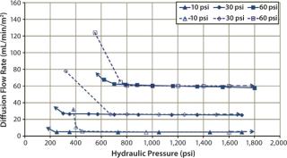
Diffusion testing at 10 psig detected a leak only when the compression pressure was 1,400 psig because no further diffusion flow-rate increase was observed (Figures 7 and 8).
In that study, cassettes were installed and compressed with both a decreasing hydraulic pressure to simulate hydraulic system leakage and an increasing pressure to simulate a normal compression cycle (Figures 7 and 8). The test with decreasing compression is represented by filled symbols with a dotted-line, and the diffusion test with increasing compression is represented by open symbols with a solid line. Arrows indicate the direction of compression — from low to high pressure or vice versa. For a system losing compression pressure (simulating leaking), the diffusion flow rate was consistently lower than for a system compressed from low to high pressure because cassettes and gaskets took a “set” and remained sealed. Those seals gave way only when the pressure was high enough to push them apart.
Temperature: Diffusion test specifications for UF membranes provided by manufacturers are usually based on testing conducted at 20–25 °C. Diffusion flow through such a membrane is proportional to the solubility and diffusion coefficient of air. Below 60 °C, diffusion flow increases 10–20% with every 10 °C increase of air temperature. The diffusion value can be correlated to test specification at 20 °C with a correction factor if flow is measured by an upstream mass flowmeter or volumetrically downstream by measuring with a graduated cylinder.
For other variations of diffusion testing — such as pressure decay tests based on the ideal gas law — the effect of temperature on a test value is even greater. It is important to maintain system temperature stability (which includes the temperature of test gas (air), wetting fluid, cassette holder, and test environment) when performing integrity test. For valid results, use test procedures or instruments that can detect such variations.
Using an Automatic Integrity Tester
An automatic integrity tester is commonly used for UF system integrity testing in a manufacturing environment. Tests are performed by automatic testers that measure upstream pressure decay (pressure loss) over fixed time intervals in agreement with the ideal gas law. Caused by diffusion or viscous flow through the closed, pressurized system, that pressure decay can be calculated using
Equation 2 under isothermal conditions.
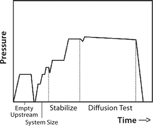
So upstream pressure loss depends on actual gas flow through the system as well as the system’s upstream volume. Typically, an automatic tester is connected to the upstream (retentate line) of a UF system. With the feed line closed, that line is pressurized to a specified test pressure. After automated measurement of upstream volume and stabilization of test pressure, the test instrument closes the gas supply so that upstream gas begins to flow through wetted pores in the membrane, leaving the system. That causes the upstream pressure drop detected by pressure transducers in the automatic tester. At a constant temperature, that change in pressure is directly proportional to the gas flow and thus used to determine the gas flow rate. Figure 9 presents a typical diffusion test sequence with an automated integrity tester.
Because that technique is noninvasive to the sterile downstream side of the system, automatic testers are used widely in integrity testing sterile filters. However, when testing large UF systems, the limited readily available upstream volume to accommodate pressure loss through their large membrane area can invalidate test results.
For example, for testing a typical 10-m2, 10-kDa UF membrane system at 30 psig, the maximum allowable diffusion flow rate is 700 mL/min. When the available upstream volume for an automatic tester is only 1,000 mL (with tester and holder directly connected), at that diffusion flow over a two-minute test duration, the expected pressure loss would be 20.6 psi (based on
Equation 2). The test machine could report such a large pressure loss as a gross leak failure.
The rule of thumb for using automated integrity testers is that the maximum allowable pressure drop should be <20% of the specified pressure, and the test time should be set so that pressure does not drop >20% of the starting test pressure. This will ensure that the test is valid and truly based on the specified test pressure.
To minimize test errors, scientists using the pressure-decay method to integrity test a UF system must take into consideration the measurement error of pressure readings, temperature variations, time, and upstream volume. For UF systems with >2.5-m2 membrane area, the best practice is to validate automatic integrity tester results for accuracy and reproducibility using a downstream volumetric or mass flowmeter. Increasing the upstream volume — e.g., by adding a pressurizable tank — or stabilization time may be required to improve the accuracy of an automated integrity test for a large system.
Testing a Large TFF System
The diffusion specification for a given module type typically is set by evaluating the distribution of diffusion values exhibited by a population of manufactured cassettes, then using the mean diffusion (plus two to three standard deviations) as an acceptable passing specification. To determine the diffusion test specification for a large UF system (process-scale holder with multiple cassettes installed), most users multiply the diffusion specification of single module by the number of modules in that system.
There will always be a difference between the mean gas flow rate and test specifications. The primary drawback for such linear scaling of the diffusion specification is that multiple cassettes increase the difference between the most likely mean gas flow rate and the upper limit of acceptable diffusion indicated by the specification, which could mask the marginal failure of a single defective filter module. That marginal damaged membrane module could give gas flow exceeding the individual test specification but still i
nsufficient to push the total flow over the total system specification (4).
Another approach is to statistically correct and lower the integrity test specifications for each membrane module in a large system, with the previously generated test result based on trending integrity test data for the same installation. An action-alert limit can be based on a large-enough data set if an observed diffusion value is above the historical trend. Diffusion values can be compared with initial values to minimize the risk of failure caused by procedural problems. This is more likely to detect a single defect module in a large system, but it could also increase the possibility of false failure.
For troubleshooting failure of a large UF system integrity test, you could perform offline testing of modules on a separate holder or load modules onto separate banks of holders that can be isolated with valves. Then you can test with a membrane area 2 for each subgroup and individually test to identify the defective module. This is a very time-consuming and difficult procedure, especially considering the time available in a manufacturing schedule. It is typically used to save good modules or to determine what may have gone wrong.
Troubleshooting
Principles of troubleshooting failed integrity tests for sterilizing-grade filters can be applied to UF systems as well. Integrity test failures can happen before or after filter use. First, the type of failure needs to be determined: gross failure (>150% of test specification) or marginal failure (<150% of the test specification). Second, test parameters are confirmed to verify that test pressure, gas, temperature, and specifications are all correct. For marginal failures, possible causes include improper wetting or flushing procedures, incorrect wetting or testing temperature, and insufficient compression. A poorly or unmaintained cassette holder can also apply less force onto cassettes as nuts wear out or hydraulic oil leaks from the system, causing integrity failure.
Gross leaks can be interpreted as a false failure or indicate real membrane defects. Possible causes of false failure are improper cassette installation with incorrect torque or compression pressure, intercassette gasket misalignment, or installations with no gaskets. Improper sealing upstream of the UF system (including piping and valves) also can contribute to a gross leak. Before integrity testing UF modules, you can perform a system integrity test by pressurizing the upstream side of your system, maintaining the filtrate valve closed. A system integrity test can then detect loss of pressure caused by leaks on the upstream side.
Real membrane defects can be caused by cleaning or storing UF modules using incompatible chemical solutions or by extreme cleaning conditions. Improper handling resulting in pinches on a cassette or gasket, foreign objects in process piping, and excessive backpressure or inlet pressure during processing or integrity testing (due to an incorrect valve-operating sequence) all can cause mechanical damage to membranes. You can identify the root cause of an integrity test problem with a proper troubleshooting decision-making process (Figure 10).
Although a diffusion flow rate that exceeds the test specification is considered a failed integrity test, an incorrectly set-up system (e.g., a closed valve) will give a falsely passing diffusion test result with zero flow rate. To prevent such false-passing results, some users set a specification for minimum diffusion flow rate ranging from >0 mL/min to 10% of the maximum diffusion flow rate specifications. Good operator training and robust standard operating procedures (SOPs) are required for getting accurate and reliable results from integrity tests. It is also important to trend batch-to-batch records and watch for any elevated diffusion value over the process runs. Collected test data help to increase the reliability of a UF unit operation.
Real Results, Real Benefits
Ultrafiltration is an important unit operation in biomanufacturing. To mitigate the risk of product loss, membranes must be free from defects, and modules must be sufficiently sealed when they are installed into a UF system. Although manufacturing release tests ensure the integrity of membranes sold, users always perform their own integrity testing before processing to check for proper installation. An in situ diffusion test is often performed using a mass flowmeter or automatic integrity tester.
Diffusion test results do not directly correlate with membrane pore size. However, theoretical calculations estimating defect size, proportion of liquid flow, and resulting retention show that performing a diffusion test before processing can significantly reduce the risk of yield loss — especially with larger membranes. Factors such as holder sealing force, gasket thickness, temperature, and test pressure affect integrity test results. Correct test parameters and procedures ensure that those results will be reliable and accurate.
For large UF systems, linearly scaling the diffusion specification increases the possibility that a diffusion test will not detect defective membranes. You can develop a lower allowable diffusion flow rate based on historical data. But doing so may not be beneficial because defects or sealing issues can lead to gross leak results instead of marginal failures. Although gross leaks can either be false failures or indicators of real membrane defects, you can systematically troubleshoot the process. Good operator training, SOPs, and integrity-test implementation would collectively increase the reliability of UF unit operations in bioprocessing.
Author Details
Seat Yee Lau, BE, is senior process engineer; Priyabrata Pattnaik, PhD, is senior technical manager; and corresponding author Bala Raghunath, PhD, is director of the Asia Biomanufacturing Sciences Network at Merck Millipore’s Biomanufacturing Sciences and Training centre, 1 Science Park Road, #02-10/11, The Capricorn, Singapore 117528; 65-6403-5314, fax 65-6403-5322; bala.raghunath@merckgroup.com.
REFERENCES
and JO Maloney. 1997.Perry’s Chemical Engineers’ Handbook, McGraw-Hill Professional, New York.




Which chemical is harmful or helps for caset failurity.
please suggest us and why?
Chemical that can impact integrity of TFF device depends on type of mebrane and polymeric components used in built of TFF device and their chemical compatibility. TFF device can be made out of PES, PVDF or Cellulose based membranes. If the chemical used in cleaning or part of the process is corrosive to the polymer used in TFF device, it will affect integrity of the device. Hence is good practice to check chemical compatibility before use.